This is a comprehensive user guide for the Wattwatchers Onboarding Application
If you would like a quick Onboarding guide including a video, try our article Use Onboarding to Commission an Auditor
Table of Contents
Switching (A6M+3SW & A6W+3SW Only)
What is Onboarding?
The Wattwatchers Onboarding application is generally used by the device installer or a support technician to configure and test the Wattwatchers Auditor devices as part of the installation and commissioning process.
This includes configuration of the device name and timezone, installation type and channel settings, and the ability to view device status and energy measurements in real-time.
The Onboarding application is accessed from a desktop or mobile device using a web browser at https://wattwatchers.app.
An internet connection from the desktop or mobile device is required to use the Onboarding application, as the Onboarding application communicates with the Wattwatchers device over the internet. No other special network settings or communications cables are required.
Accessing the Onboarding Application
The Onboarding application is accessed from a desktop or mobile device using a web browser at Wattwatchers App.
Enter your username and password and press the Login button to access the Onboarding application. If you do not know your account credentials, you can follow the steps outlined in our Quick Answers: How do I reset my password?.
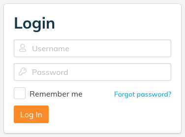
The provider of your Wattwatchers device is able to create an account for you, or you can contact Wattwatchers support to request access.
When logging in, if you have access to other Wattwatchers applications, you may be shown the application icons for Fleet, Onboarding and Dashboard. Select the Onboarding icon to continue to the Onboarding application.

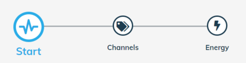
Onboarding Process Overview
After entering the device Serial Number, the Onboarding application guides the user through a series of steps to set up the device and complete a successful installation.
- Start - provides access to the device information including custom device name and timezone configuration.
- Channels - allows the configuration of the electrical installation type and the Current Transformer (CT) clamps.
- Energy - displays the real-time energy consumption, plus voltage and power factor information used to validate that all of the CT clamps and circuit monitoring channels are working as expected.
When you have Switching or Modbus, you will see the respective additional tabs
- Switching (A6M+3SW / A6W+3SW models only) - allows the user to configure and turn the switches on and off for commissioning and testing.
- Modbus (A6M+One models only) - provides real-time energy consumption from a connected supported Modbus device.
For a new installation, the installer should work through each step to complete the installation. For testing and diagnostic tasks, it also is possible to jump to any one of the steps at any time.
These steps are shown either on the left-hand side or at the top of the screen depending on the browser and screen size.
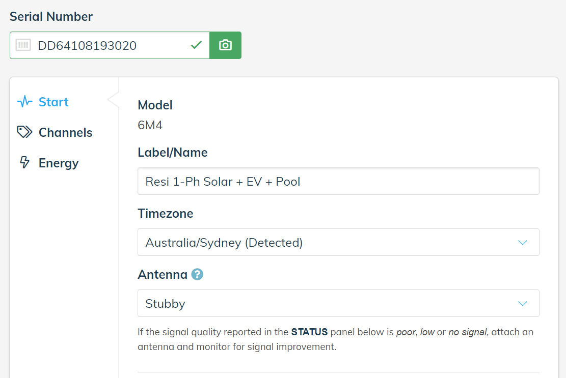
Desktop device users will normally see the steps shown on the left side of the screen, as shown below.
DESKTOP VIEW
Mobile device users will see the steps shown at the top of the screen as shown below.
MOBILE VIEW
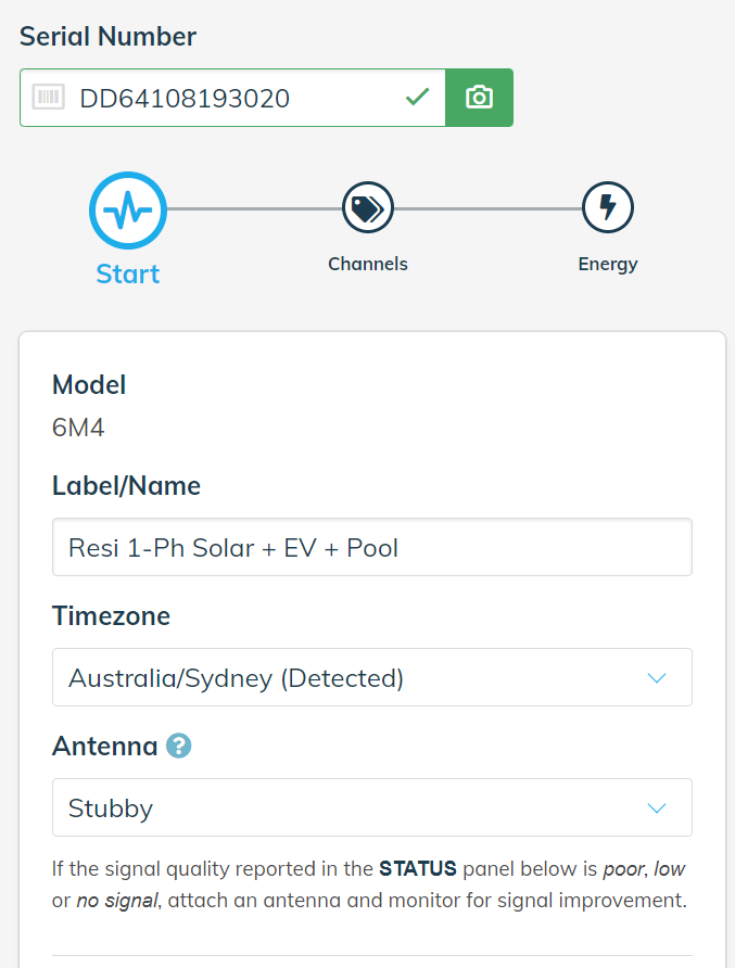
Because Onboarding is a mobile-first application, we will show most of the screenshots in this article using the mobile layout.
If any step requires action or an error is identified, then the user is alerted with the red exclamation mark (!) icon to indicate a configuration issue or missing information has been identified.
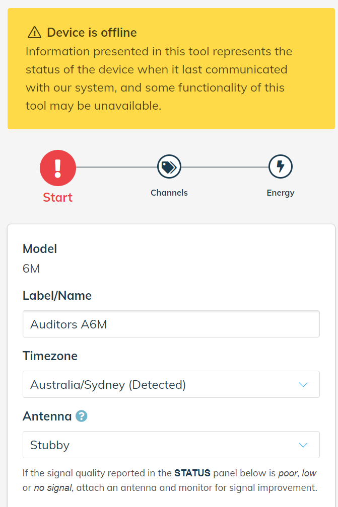
In the following example, the Start step is highlighted with the red alert icon because the device is offline.
When all of the steps have been completed and no icons are red, the installation is considered successful and complete.
As you make changes, the Save Changes button will appear at the top and bottom of the screen. If the Save Changes button is not pressed, any changes to that step will be lost and will need to be re-entered again.

Click on the Cancel button if you do not wish to save any changes and return to the settings currently stored in the device.
The following sections provide more detailed information on each step.
Before Starting
The Wattwatchers Auditor device must be powered on and be communicating successfully with the Wattwatchers platform in order to use the Onboarding application.
If the device is offline or not currently communicating with the Wattwatchers platform, a message will appear at the top of the page as shown.
There is an additional warning that is also be shown on the Energy section in this situation.
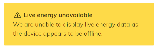
If any of these messages appear, please review the device installation instructions and confirm that the device is working correctly before proceeding.
Serial Number Search
Enter the device serial number to start the Onboarding process.
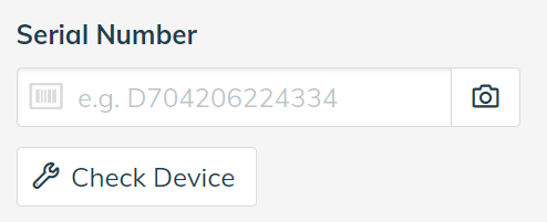
When a valid device serial number is entered, the first step of the Onboarding process will be automatically displayed.
If you are unable to access your device and the message “You are not authorised to access this device” is displayed, please check the device serial number is correct and enter the correct value. If the issue persists, please contact Wattwatchers support.
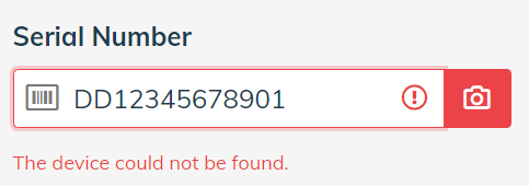
If the message “The device could not be found” is displayed, please check the device serial number is correct and enter the correct value. If the issue persists, please contact Wattwatchers support.
Note: The camera button to the right of the serial number field previously provided access to open the device camera (such as on a mobile device) to take a picture of the device barcode. This feature is currently unavailable. (Jan 2021)
Start
The Start step displays the device label and timezone type information, as well as device communications status information.
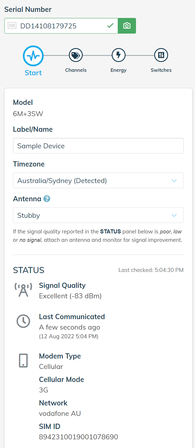
The Label/Name field is used to enter a user-friendly name for the device. This is a free text field and information such as the customer name or address is generally entered in this field.
The Timezone field should automatically detect the local timezone of the location where the device is installed. Ensure this field is correct, or drop down this field to select the correct timezone.
The Antenna type must be selected. The available options are:
- No antenna: No antenna connected to the Auditor.
- Stubby: Standard right angle whip antenna connected directly to the front of the Auditor.
- External: Optional antenna mounted outside the enclosure and connected by a cable to the Auditor.
In the Status section, the information on the device signal strength, last communication time, and modem information also is displayed.
For 3G and 4G devices, it is essential to ensure that the device has sufficient signal strength for reliable operations. If the device has inadequately low signal strength, then an error message will be displayed as below.
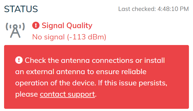
A low signal strength issue also will result in an alert condition on the Start step and must be resolved by improving the signal strength (such as by installing an external antenna) before completing the installation.
Click on the Save Changes button before moving to the next step.
Channels
The Channels step allows the device to be configured for Single Phase, Two Phase or Three Phase electrical systems and to configure and label each current transformer for circuit level monitoring.
Initially all channels are set to “Not Connected” allowing the Install Type and desired circuits to be configured for each site.
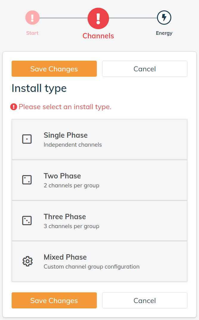
Select the Install Type from the following options:
- Single Phase - for sites with a Single Phase incoming supply and supports up to 6 independent channels.
- Two Phase - for sites with a Two Phase incoming supply and supports three groups of Two Phase circuits. Note that only Group 1 (CH1 and CH2) and Group 2 (CH4 and CH5) should be used with this option.
- Three Phase - for sites with a Three Phase incoming supply and supports two groups of Three Phase circuits.
- Mixed Phase - custom channel grouping. Note that this is not fully supported by the Onboarding tool as yet (Jan 2021) and you should contact Wattwatchers support noting your configuration requirements to arrange a final set up of the device.
A channel group is a collection of circuits that are monitored as a group. This is used to group circuits that form part of a Two Phase or Three Phase circuit.
For each channel group, the following inputs are required.
Category
Choose a Category from the drop down list provided.
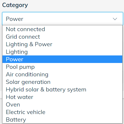
The categories are defined as follows:
- Not connected - select this option for any channels that will not be used.
- Grid Connect - this is used to indicate the channel is monitoring the main connection to the electricity grid (import and export). At least one channel must be set to Grid Connect for most installations.
- Lighting & Power - used for combined lighting and power circuits (legacy).
- Lighting - used for circuits with lighting equipment only.
- Power - used for circuits with general power equipment only - such as domestic or commercial power outlet circuits.
- Pool Pump - for dedicated circuits monitoring a pool pump.
- Air Conditioning - for dedicated circuits monitoring air conditioning.
- Solar Generation - for dedicated circuits monitoring solar generation or hybrid solar and battery energy storage systems.
- Hot Water - for dedicated circuits monitoring Hot Water.
- Oven - for dedicated circuits monitoring an Oven.
- Electric Vehicle - for dedicated circuits monitoring an electric vehicle charger.
- Battery - for dedicated circuits monitoring a battery energy storage system. Do not use this option for hybrid solar and battery energy storage systems - use the Solar Generation item.
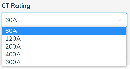
CT Rating
The CT Rating is a drop down box with several options ranging from 60A to 600A. It is important that the option selected matches the actual rating of the CTs installed with the Auditor device to produce accurate readings.
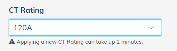
Note that when saving changes for the CT Ratio, this process can take up to 2 minutes and a message pops up at the top of the screen to confirm the action is in progress.

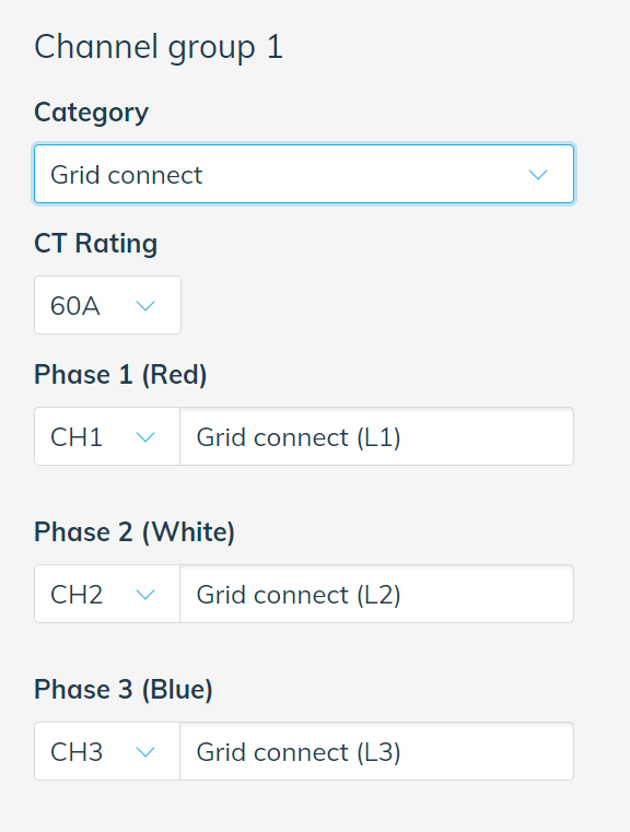
Where an Install Type with channel groups has been selected, the CT Rating applies to all of the channels in that group, such as the following Three Phase example. Note that the same CT rating must be physically installed on Channels 1, 2 and 3 that form the group.
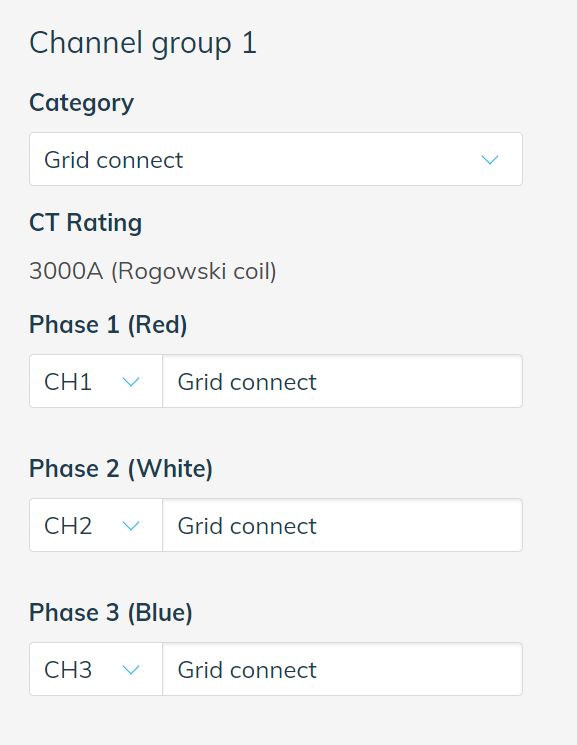
Note that for Auditor devices with Rogowski Coil inputs, the CT Rating is automatically set to 3000A and can not be changed. This is shown in the example below.
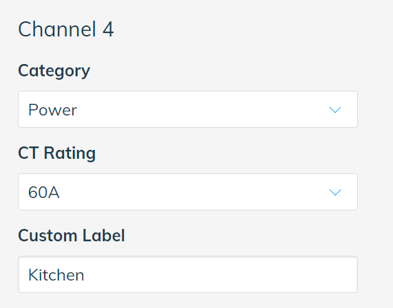
Custom Label
The Custom Label field is used to assign a custom label to each channel on the device.
For a new device, the Custom Label is automatically set to the same value as the Category field. The Custom Label field can then be changed if required to a more descriptive label specific to the site.
For example, in the image below, the Category of “Power” was chosen but the Custom Label was updated to “Kitchen” as the name of the circuit being monitored at this site.
Click on the Save Changes button before moving to the next step.
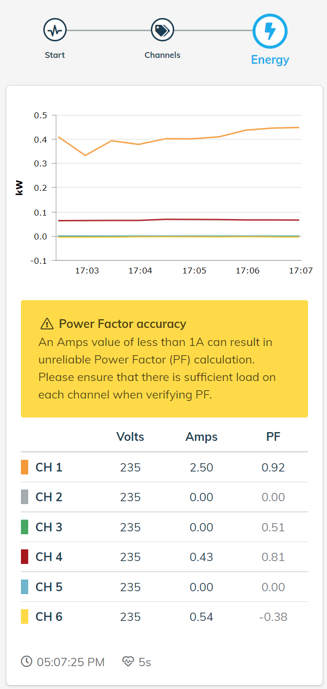
Energy
The Energy step shows both a chart and table of the real time values for each of the channels set up in the previous section. This is used to verify that the measurements and direction of each channel are correct.
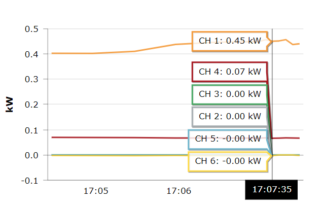
On the chart, the power consumption in kilowatts (kW) of each channel is displayed in real time. Only a short period of time is displayed to provide information about what is currently happening at the site.
Positive values on the kW chart generally indicate normal energy consumption on that channel. Negative values on the kW chart generally indicate reverse power flow on that channel.
However, note that dedicated solar circuits are generally installed so that energy generated by the solar system is positive at the individual channel level, but that the Grid Connect channel will show negative kW when exporting energy to the grid.
The detailed values of the chart can be displayed by clicking on the chart lines (mobile or desktop users) or by hovering over the chart lines with the mouse pointer (desktop users only).
The table below the chart provides a table of each of the channels’ values for voltage (Volts), amperage (Amps), and power factor (PF) of each channel with constantly updating values.
PF is the Power Factor referring to the ratio between real or ‘useful’ power (kW) to the total ‘apparent’ power (kVA) consumed by the circuit. It is a measure of how efficient a system is at converting electrical power to useful work output. The ideal Power Factor is 1.00, also known as unity power factor.
Positive PF generally indicates consumption of energy by loads on that circuit.
Negative PF generally indicates there is energy being exported or generated by that circuit, such as from a solar or battery system.
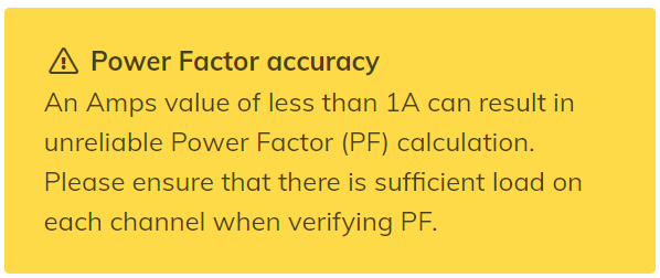
A notification is always displayed if any channel has less than 1A to remind the user that at least 1A should be measured on each channel to have a useful PF value.
The Clock and Heartbeat icons at the bottom of this page are used to display information about the data being received from the device.

The value next to the Clock icon is the timestamp for the data last received from the device. This can be used to confirm that the data being received has been received recently and has the correct current local time of your desktop or mobile device.
The value next to the Heartbeat icon is the rate at which data is being transmitted by the device. A value of 30s indicates the device is sending data every 30 seconds.
As part of the Onboarding process, the device will transition from transmitting data every 30 seconds to transmitting data every 5 seconds and remain in this state until the Onboarding process is complete. While the devices is switching modes, this will be indicated by a value of 30s...5s.

When the device is transmitting data every 5 seconds, this is indicated by a value of 5s with the Heartbeat icon as shown below.

Switching (A6M+3SW & A6W+3SW Only)
The Switching step provides access to configure and operate the switching outputs on the A6M+3SW and A6W+3SW devices. This allows configuration of switches for load control and demand response applications as well to activate the switches for commissioning and testing.
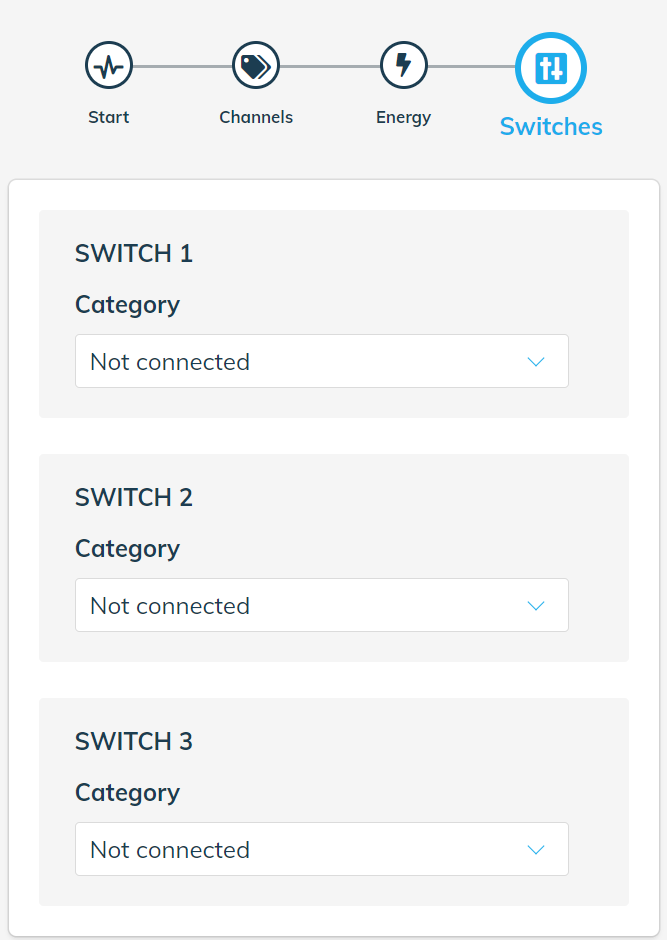
There are 3 independent switches available that each require configuration. These are shown in the sections noted by the headings SWITCH 1, SWITCH 2 and SWITCH 3.
For each switch, first select the category for which you will be using the switching control. As well as this, a custom label can be applied for ease of use.
The Category field is used to select the type of switch being used.
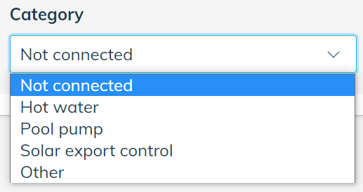
- Not connected - select if the switching output is not being used.
- Hot Water - used for Hot Water control applications.
- Pool Pump - used for Pool Pump control applications.
- Solar export control - used for Solar inverter demand response and export limit controls. Please refer to our separate articles available on Solar Inverter Remote Disconnection Control for SA Smarter Homes.
- Other - used for any other type of control application.
The Custom Label field is used to give a user-friendly name to the control circuit. By default, the same label as the Category is applied for new devices, but can be changed to any preferred value.
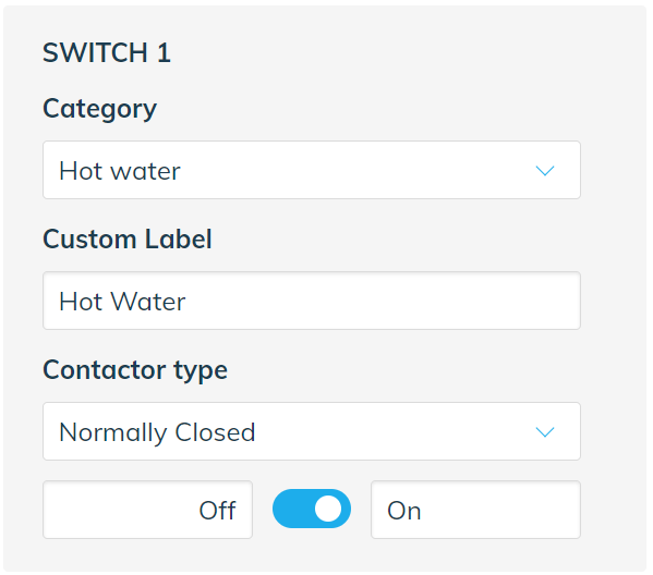
The Contactor Type field refers to the switching position of the contactor associated with the output. Whether it is Normally Open (NO) or Normally Closed (NC) determines whether power flows through the switch when the switch state is changed.
Note also that when the Contactor Type field is changed, the switch icon and On/Off labels also are updated to match. For example, when a Normally Open switch coil is energised, the switching output is turned On. Conversely, when a Normally Closed switch coil is energised, the switching output is turned Off.
The following shows an example where the device has been configured for a Hot Water control application.
The switch icon provides a method for turning the switching output On and Off, depending on the Contactor Type that is selected. The switch colour matches the the switching status LED indicators on the Auditor device itself.
Switch Output Deactivated (Red)

Switch Output Activated (Blue)

Note that once the switching button is activated, the device should change state within 5 to 10 seconds. However, the switch icon will become grey and unavailable for up to 30 seconds while the operation of the switch is confirmed by the Onboarding application.
Once the switch is ready for another operation, the control will return to normal colour and can be toggled again as required.
Custom labels can also be added in the On and Off fields if required to make the switching states clear.
Note that if the Solar export control option is selected, additional fields are required. Please refer to our separate articles available on Solar Inverter Remote Disconnection Control for SA Smarter Homes.
Modbus (A6M+One Only)
The Modbus step provides information on supported devices connected to the Modbus device including the type of device and current values.
The Modbus step does not require any user input as the connected device will be detected automatically. Information on the connect device type, including an image of the device will be displayed.
The following image shows an example for a Three Phase PMC-340B metering device connected and sending data successfully.
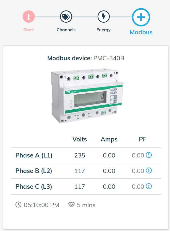
A table of current values is displayed similar to the Energy step below the device information and image section. Information on Voltage (Volts), Current (Amps) and Power Factor (PF) is displayed for the available parameters of the device. For example, a Three Phase device will show data for Phase A (L1), Phase B (L2) and Phase C (L3), whereas a Single Phase device will show data for Channel 1 only.
The following image shows an example for a Single Phase PMC-220 metering device connected and sending data successfully.
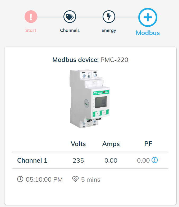
The Clock and Heartbeat icons at the bottom of this page are used to display information about the data being received from the device.

The value next to the Clock icon is the timestamp for the data last received from the device. This can be used to confirm that the data being received has been received recently and has the correct current local time of your desktop or mobile device.
The value next to the Heartbeat icon is the rate at which data is being transmitted by the device. A value of 5 mins indicates the device is sending data every 5 minutes.

Modbus devices only support transmission once every 5 minutes.
If there is an issue with the connection between the Auditor and Modbus device, then the following message is displayed.
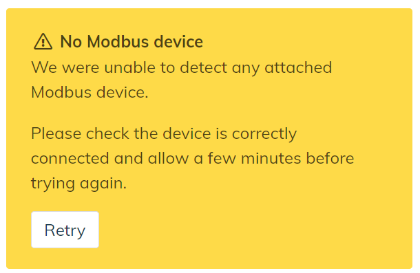
The connections between the Auditor and Modbus devices should be checked and if the issue persists please contact Wattwatchers support.
More Information or Support
Please contact Wattwatchers support.