Quick Links
Background
Wattwatchers is a Technology Partner of SA Power Networks in its capacity as a 'Relevant Agent' using Wattwatchers devices to perform the remote disconnection and reconnection under the South Australian Smarter Homes program.
Refer to our information on Solar Inverter Remote Disconnection Control for SA Smarter Homes for additional information and other supported methods and equipment.
Relevant Agent Selection
The solar installer must select the Relevant Agent and Wattwatchers as the relevant technology when the equipment is registered with SA Power Networks as part of the standard network application process for grid-connected solar installations.
These steps include:
- Small Embedded Generation (SEG) approval using Wattwatchers as the relevant technology.
- Installation and commissioning of the solar disconnection equipment as per the relevant application notes.
- Submit the Electrical Certificate of Compliance (eCoC) and select Wattwatchers as the relevant technology.
More information on this can be found on the SA Power Networks Relevant Agent website.
Hardware Overview
Wattwatchers Auditor Device
The Wattwatchers Auditor 6M+3SW is used in combination with a Contactor to send the DRM Control signals to the inverter.
The A6M+3SW switching outputs are designed to support application with Contactors supplied by Wattwatchers with a 240V coil control voltage. The A6M+3SW switching outputs do not support a direct connection to the inverter DRM interface and must be used with an external Contactor as described in this Application Note.
The Contactor is installed to connect two pins together on the solar inverter to assert the DRM0 (disconnect) or DRM5 (stop generation) signal.
Contactor Ratings
The Contactor must be rated to support the maximum voltage and current required for the DRM port of the solar inverter equipment. Please refer to the solar inverter documentation to confirm these requirements.
Wattwatchers supplies Contactors in the following configurations:
- Single Phase applications: Two Pole 240V 25A (1x NO with 1xNC) with 240V coil
- Three Phase applications: Three Pole 240V 25A (NO or NC) with 240V coil
Please contact us if other Contactor ratings or configurations are required.
Step 1 - Solar Inverter Configuration
PVS-10/33 - Three Phase Inverter
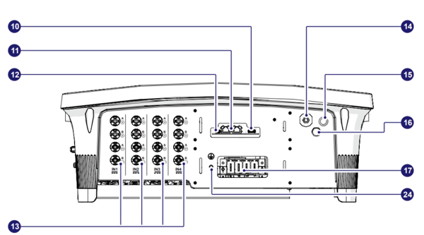
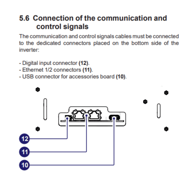
This command can be used to DRM0 functionalities via an external command by means the Digital input and RS485 connector (12). The functionality must be enabled in the integrated web user interface.
The AS/NZS 4777.2 standard contains requirements related to grid stability and remote system control by the utility. One of these requirements is demand response mode for zero export (DRM 0), which reduces export to grid to zero upon command from the utility. This is done by connecting an external Demand Response Enabling Device (FIMER DRM0 Interface) to the inverter digital input.
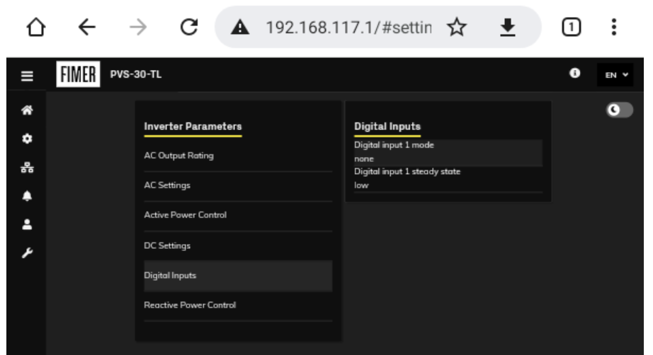
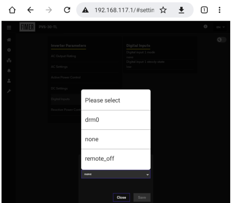
Enabling the DRM0 function in the inverter web interface
Use the Inverter Parameters > Digital Inputs > Digital input 1 mode and select the "drm0" option as shown below.
PVS-50/60 – Three Phase Inverter
Remote switch-on/switch-off
This command can be used to perform a software switch off/switch on the inverter via an external (remote) command.
The switching on of the inverter, when this functionality is activated, besides being dictated by the presence of normal parameters which allow the inverter to be connected to the grid, also depends on the external control for switching on/off.
Remote control connection
The connection and disconnection of the inverter to and from the grid can be controlled through external control.
The function must be enabled in the relevant menu through the Aurora Manager Tools software. If the remote control function is disabled, the switching on of the inverter is dictated by the presence of the normal parameters which allow the inverter to connect to the grid.
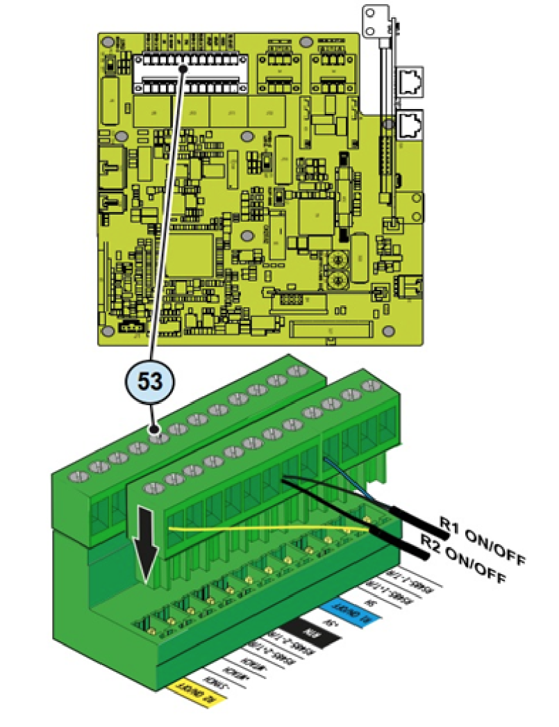
If the remote control function is operating, besides being dictated by the presence of the normal parameters that allow the inverter to connect to the grid, the switching on of the inverter also depends on the state of the R1 ON/OFF and R2 ON/OFF terminals compared to the RTN terminal present on the a11 connector of the communication and control board 35 .
When one of the R1 ON/OFF or R2 ON/OFF signals is brought to the same potential as the RTN signal (i.e. by making a short circuit between the two terminals of the connector), this causes the inverter to disconnect from the grid.
The connections of these controls are made between the “R1 ON/OFF” and the "R1 ON/OFF" inputs compared to the common "RTN" signal.
Since this is a digital input, there are no requirements to be observed as regards cable cross-section (it only needs to comply with the sizing requirement for passing cables through the cable glands and the terminal connector).
Enabling the function in the web server user interface.
Connect your device (Phone, Tablet/PC) to the inverters wifi channel. See Installation Guide.
Open web interface. See Installation Guide.
Choose the setting icon in the menu.
Enable Digital Inputs Remote ON/OFF.


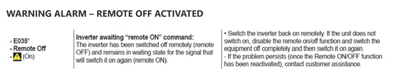
WARNING ALARM – REMOTE OFF ACTIVATED
PVS-100/120 – Three Phase Inverter
Remote switch-on/switch-off
This command can be used to perform a software switch off/switch on
the inverter via an external (remote) command.
The switching on of the inverter, when this functionality is activated, besides being dictated by the presence of normal parameters which allow the inverter to be connected to the grid, also depends on the external control for switching on/off.
Remote control connection
The connection and disconnection of the inverter to and from the grid can be controlled through external control.
The function must be enabled in the relevant menu of the Web User Interface. If the remote control function is disabled, the switching on of the inverter is dictated by the presence of the normal parameters which allow the inverter to connect to the grid.
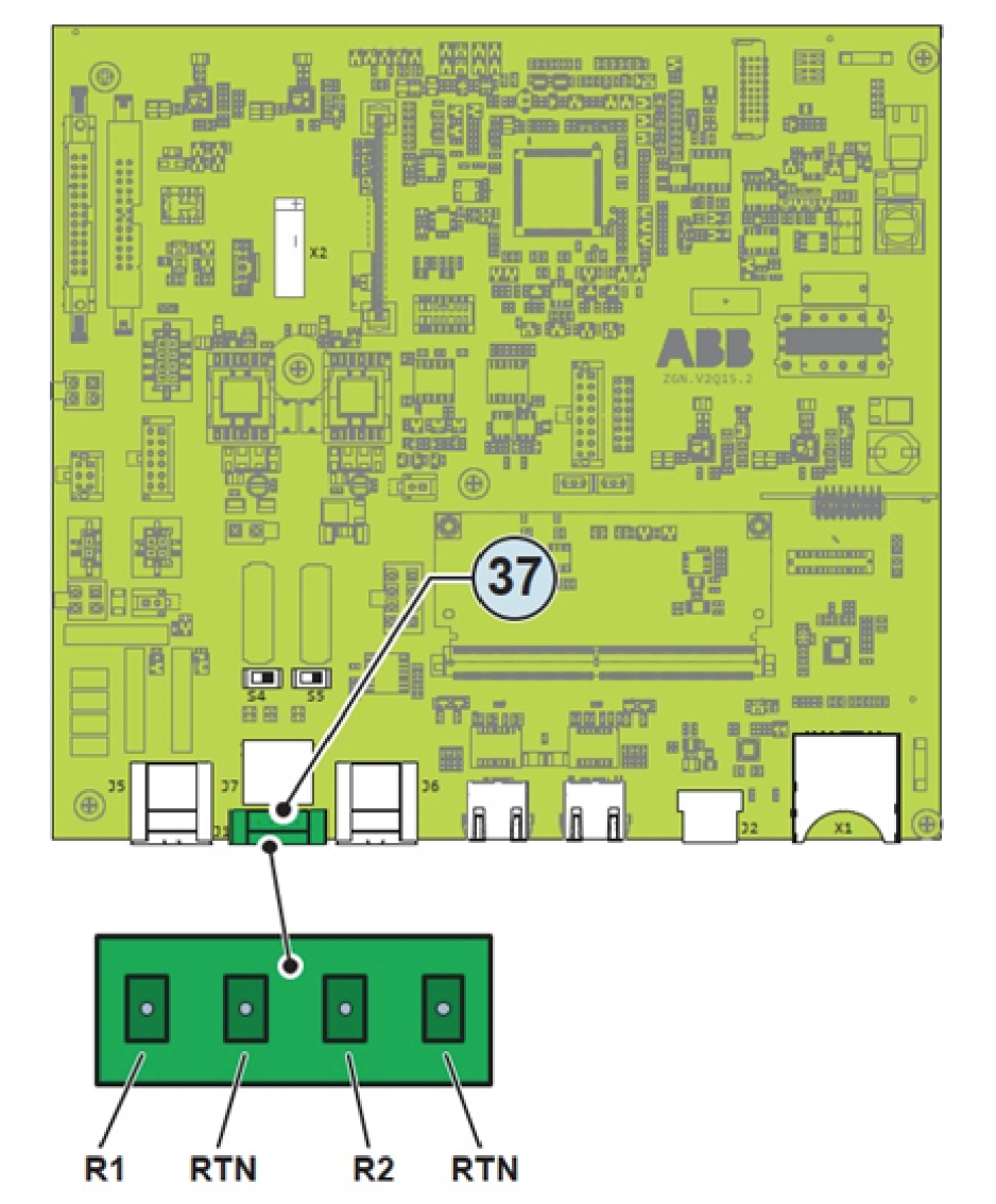
If the remote control function is operating, besides being dictated by the presence of the normal parameters that allow the inverter to connect to the grid, the switching on of the inverter also depends on the state of the R1 and R2 terminals compared to the RTN terminal present on the Connector 37 of the communication and control board 28.
When one of the R1 or R2 signals is brought to the same potential as the RTN signal (i.e. by making a short circuit between the two terminals of the connector), this causes the inverter to disconnect from the grid.
The connections of these controls are made between the R1 and the R2 inputs compared to the common RTN signal.
Since this is a digital input, there are no requirements to be observed as regards cable cross-section (it only needs to comply with the sizing requirement for passing cables through the cable glands and the terminal connector).
Enabling the function in the web server user interface
Connect your device (Phone, Tablet/PC) to the inverters wifi channel. See Installation Guide.
Open web interface. See Installation Guide.
Choose the setting icon in the menu.
Enable Digital Inputs Remote ON/OFF.
WARNING ALARM – REMOTE OFF ACTIVATED
Step 2 - Wattwatchers Auditor Installation
The Wattwatchers Auditor 6M+3SW is installed in the customer switchboard with an appropriate protection device such as an RCBO or Breaker depending on the local jurisdictional requirements.
The Contactor is installed to connect two pins together on the Solar Inverter DRM interface to assert the DRM0 (disconnect) signal.
Current Transformers are installed on the Solar AC Supply to monitor the generation and also on the Main Incoming Supply to monitor the total site load.
The equipment is installed as per the information provided in the Wattwatchers A6M+3SW Quick Start Guide and the Wiring Diagrams as follows.
DRM0 Control for Three-Phase Supply with Three-Phase Solar Inverter
Please refer to the solar inverter documentation to confirm the connections to the solar inverter DRM interface.
Step 3 - Wattwatchers Auditor Configuration
The Wattwatchers Onboarding application is used to configure the device as part of the normal installation process.
The following settings are required in the Wattwatchers Onboarding application for the SA Smarter Homes requirements.
Site Configuration
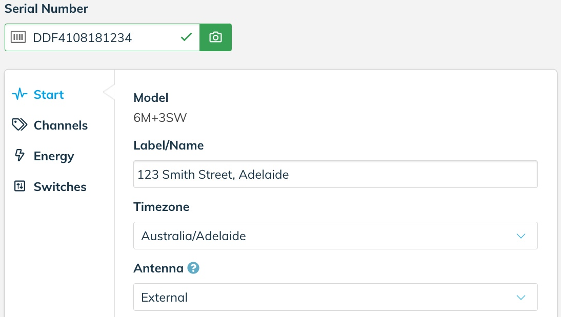
In the Start section of the Onboarding application, set the site address and timezone as follows.
Label/Name: Set this as the customer address including street name and suburb (eg: 123 Smith Street, Adelaide)
Timezone: Australia/Adelaide (or relevant local timezone if not installed in South Australia)
The following shows an example configuration.
Press the Save button to store this configuration before moving to the next step.
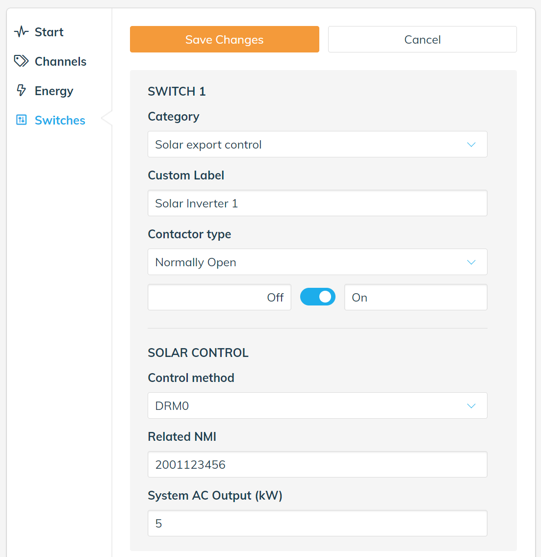
Switches Configuration
In the Switches section of the Onboarding application, select the relevant Switch device (Switch 1, Switch 2 or Switch 3) depending on which switching interface the Contactor has been wired into. In all of the example wiring diagrams, this is Switch 1.
Category: Solar export control
Custom Label: User defined label (eg: Solar Inverter 1)
Contactor Type: Normally Open
Solar Control Parameters
Control Method: DRM0 or DRM5
Related NMI: Customer NMI (if available)
System AC Output (kW): Solar AC Output Rating (in integer or decimal format eg: 5 or 5.0)
The following shows an example configuration.
Press the Save button to store this configuration before moving to the next step.
Step 4 - System Commissioning Test
Using the Wattwatchers Onboarding application, the following process is performed.
- Navigate to the Energy section of the Onboarding application to display the current energy being generated by the solar system and note this value should be a positive value when the system is generating normally.
- Navigate to the Switches section of the Onboarding application and activate the disconnection function by selecting the control slider for the relevant switch and selecting ON.
- The Contactor should operate within around 5-10 seconds to signal the solar inverter equipment to disconnect or stop generation.
- Navigate to the Energy section of the Onboarding application to display the current energy being generated by the solar system and ensure this value is zero.
- Navigate to the Switches section of the Onboarding application to reconnect the solar system by selecting the control slider for the relevant switch and selecting OFF.
- The Contactor should operate within around 5-10 seconds to reconnect the solar inverter equipment.
- Navigate to the Energy section of the Onboarding application to display the current energy being generated by the solar system and note this value should increase as the solar inverter returns to normal operation.
Step 5 - Relevant Agent Registration
Wattwatchers supports multiple Relevant Agents. In the following example, SA Power Networks has been used as the Relevant Agent.
Please confirm the Relevant Agent and relevant technology selections with your Solar Retailer.
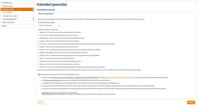
Solar Retailer Example with SA Power Networks as Relevant Agent
When registering the Embedded Generation equipment on the SA Power Networks Portal, select the preferred Relevant Agent (SA Power Networks in this example) with the option for Wattwatchers that is "Internet connected Wattwatchers Auditor 6M or 6W device with Contactor switching for all inverters, or connected to inverters DRM port for supported models" in this example.
More Information or Support
Please contact us for additional information or assistance.