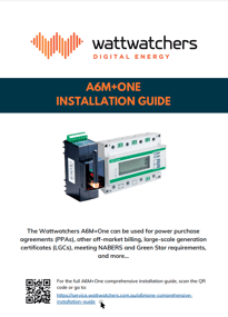
A6M+One INSTALLATION GUIDE 2023
Download the full A6M+One installation manual from the link.
This comprehensive guide is intended to support purchasers, owners and installers of the A6M+One, which is technically referred to as A6M+One (6M4/MB), single- and three-phase billing solutions to effectively install the hardware equipment.
A6M+One comprehensive installation guide
Important Information
- You must select the correct meter type for your application. Refer to the Solution Selection Guide for more information.
- The CTs used for the CET Meter and Wattwatchers Auditor devices are not compatible or interchangeable and may cause damage or create a hazardous situation if installed incorrectly.
- If you wish to monitor non-billing circuits, then you need to order the correct sized Current Transformers for the Wattwatchers Auditor device separately.
How to use this guide
This guide explains each of the features and connections of the equipment one component and set of connections at a time. It is necessary to read and understand different parts of this document depending on your application.
The following steps are recommended when using this document.
- Electrical Safety Warning
- Read the section relevant to your A6M+One bundle:
- A6M+One Single-Phase billing bundle, or
- A6M+One Three-Phase Direct Connect billing bundle, or
- A6M+One Three-Phase CT billing bundle
- Read the section relevant if you are using the additional non-billing circuit monitoring:
- Refer to the complete system wiring diagrams.
- Refer to the additional detailed documentation attached to this article if required.
Electrical safety warning
All installation work must be completed by a qualified electrician holding a valid electrical license in the applicable State and Distribution Network Service Provider (DNSP) jurisdiction.
The following installation instructions offer guidance specific to the A6M+One bundle hardware only.
Electricians should consider their own experience and seek additional support or clarification where necessary.
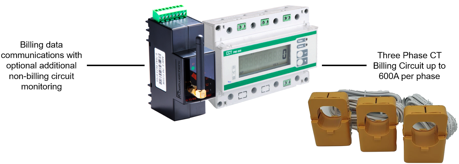
What is the A6M+One?
The Wattwatchers A6M+One billing solution combines the Wattwatchers Auditor A6M 4G device with an Australian NMI M-6 Pattern Approved revenue meter to provide real-time billing data and additional non-billing circuit monitoring capability for applications such as:
- Solar Large-scale generation certificate monitoring (LGCs)
- Solar Power Purchase Agreements (PPAs)
- EV charging monitoring
- Embedded networks
- Microgrids
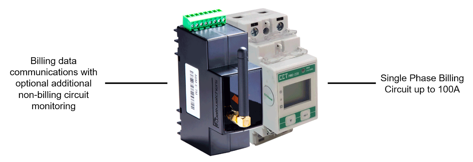
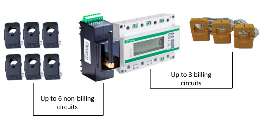
The A6M+One billing solution is a compact, DIN-rail mounted bundle in either single phase or three phase configurations. Each bundle includes:
- 1x Wattwatchers A6M+One (6M4/MB) device with Modbus interface for connection to the CET billing meter and supporting monitoring of up to 6 circuits for non-billing applications
- 1x CET NMI M-6 pattern approved revenue meter in one of the following configurations for billing applications:
- Single-Phase Direct Connect Meter, or
- Three-Phase Direct Connect Meter, or
- Three-Phase Current Transformer Meter.
It is important to be aware that for all options, the included CET meter is capable of measuring one billing circuit only. For example, this may be the AC output of a single solar inverter or the total output of multiple inverters at a solar AC main switch.
Should you need to monitor more than one billing circuit, then a separate A6M+One bundle will be required for each additional billing circuit.
A6M+One Single Phase billing bundle
The A6M+One Single-Phase billing bundle includes:
- 1x Wattwatchers A6M+One (6M4/MB)
- 1x CET PMC-220 Single Phase Billing Meter
This version of the solution is suitable for use with a billing circuit rated up to 63A and wire size up to 25mm2 cross-sectional area (5.6mm wire diameter).
For detailed technical information on the CET PMC-220 meter, please refer to the User Manual.
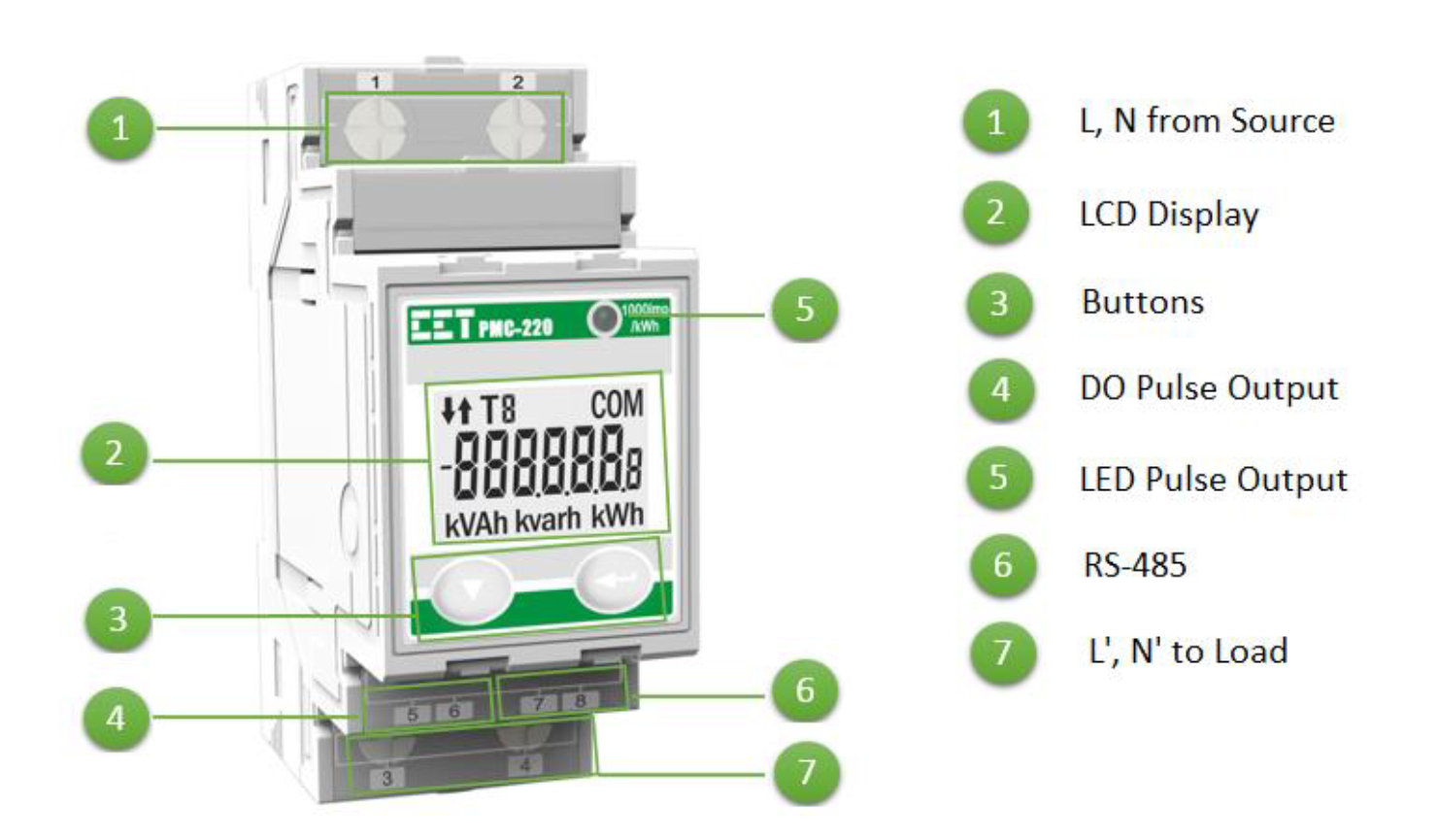
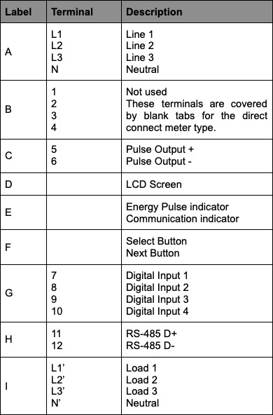
CET PMC-220 Single Phase Meter Overview
CET PMC-220 Wiring Overview
The billing circuit cables are connected directly through the CET meter without use of external current transformers (CTs).
The A6M+One device should also be installed with a single-phase breaker or RCBO with rating of ≤ 10A for protection and isolation of the power and voltage reference connections as per the local jurisdictional requirements.
The CET PMC-220 meter is rated for 63A and should be protected by an upstream main switch or fuse with the same or lower rating.
Applications with solar generation (e.g., PPAs and LGCs)
When the CET PMC-220 meter is being used to monitor solar generation, the solar generation output is connected to terminals 1 and 2 and the grid or supply breaker is connected to terminals 3 and 4. Please refer to the diagram below. Electricians must consider this hardware in context of the broader electrical installation on which they are working and comply with all relevant codes and standards as applicable to their jurisdiction. In Australia this includes, but is not limited to, the current release of AS/NZS 3000 (Australia/New Zealand Wiring Rules) and any specific DNSP requirements.
This is to ensure that the solar generation is recorded as positive energy flowing through the meter.

CET PMC-220 Single-Phase Meter for solar generation applications
Applications with load (e.g., EV Charging, tenant consumption monitoring)
When the CET PMC-220 meter is being used to monitor load consumption, the grid source or incoming supply breaker is connected to terminals 1 and 2 and the load is connected to terminals 3 and 4. Please refer to the diagram below.
This is to ensure that the consumption is recorded as positive energy flowing through the meter.

CET PMC-220 Single-Phase Meter for consumption applications
Modbus communications connection to Wattwatchers A6M
The RS-485 Modbus communication from the CET PMC-220 meter is connected to the Wattwatchers A6M+One interface by connecting the data terminals together as shown.
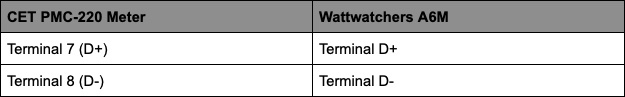
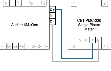
The shield (ground) terminal S of the Wattwatchers A6M does not need to be connected.
A 120Ω termination resistor is included with the CET meter that is optional and is not normally required for short cable lengths.
A6M+One Three Phase Direct Connect billing bundle

The A6M+One Single Phase billing bundle includes:
- 1x Wattwatchers A6M+One (6M4/MB)
- 1x CET PMC-340-BA Three-Phase Billing Meter
This version of the solution is suitable for use with a billing circuit rated up to 100A per phase and wire size up to 35mm2 cross-sectional area (6.6mm wire diameter).
For detailed technical information on the CET PMC-340 meter, please refer to the User Manual.
CET PMC-340-BA Three Phase Direct Connect Meter Overview

CET PMC-340 Three-Phase Direct Connect Wiring Overview
The Three-Phase direct connect version of the solution is suitable for use with a billing circuit rated up to 100A per phase and wire size up to 35mm2 cross-sectional area.
The billing circuit cables are connected directly through the CET meter without use of external current transformers (CTs).
The CET PMC-340-BA meter is rated for 100A and should be protected by an upstream main switch or fuse with the same or lower rating.
It is important that the wiring of the billing circuit through the CET PMC-340-BA is done in the correct phase order and in the correct direction.
The source is always the relevant supply side of the circuit (e.g., grid, solar inverter or generator).
Failure to connect with the correct phase order and orientation will result in inaccurate power readings such as negative power and incorrect power factor. As this is a series connection, it is possible that damage may occur to equipment or other loads if phases are accidentally mixed at the input and output terminals.
For detailed technical information on the CET PMC-340 meter, please refer to the User Manual.
Applications with solar generation (e.g., PPAs and LGCs)
When the CET PMC-340 meter is being used to monitor solar generation, the solar or generation output is connected to the L1, L2, L3 and N terminals on the top of the meter and the grid or supply breaker is connected to the L1’, L2’, L3’ and N terminals on the bottom of the meter. Electricians must consider this hardware in context of the broader electrical installation on which they are working and comply with all relevant codes and standards as applicable to their jurisdiction. In Australia this includes, but is not limited to, the current release of AS/NZS 3000 (Australia/New Zealand Wiring Rules) and any specific DNSP requirements.
This is to ensure that the solar generation is recorded as positive energy flowing through the meter.

CET PMC-340 Three Phase Direct Connect Meter for solar generation applications
Applications with load (eg: EV charging, tenant consumption monitoring)
When the CET PMC-340 meter is being used to monitor load consumption, the grid source or incoming supply breaker is connected to the L1, L2, L3 and N terminals on the top of the meter and the load is connected to the L1’, L2’, L3’ and N’ terminals on the bottom of the meter.
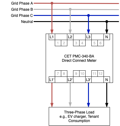
CET PMC-340 Three-Phase Direct Connect Meter for consumption applications
Modbus communications connection to Wattwatchers A6M
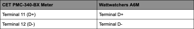
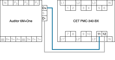
The RS-485 Modbus communication from the CET PMC-340 meter is connected to the Wattwatchers A6M Modbus interface by connecting the data terminals together as shown.

The shield (ground) terminal S of the Wattwatchers A6M does not normally need to be connected.
A 120Ω termination resistor is included with the CET meter that is optional and is not normally required for short cable lengths.
A6M+One Three Phase CT billing bundle
The A6M+One Single Phase billing bundle includes:
- 1x Wattwatchers A6M+One (6M4/MB)
- 1x CET PMC-340-BB Three-Phase Current Transformer Billing Meter
- 3x 600A/5A Current Transformers
The CET PMC-340-BB billing meter is suitable for use with a billing circuit rated up to 600A per phase. This version requires separate 600A split-core orange CTs specific to the CET meter that are included with this bundle.
For more detailed technical information on the CET PMC-340 meter, please refer to the User Manual.
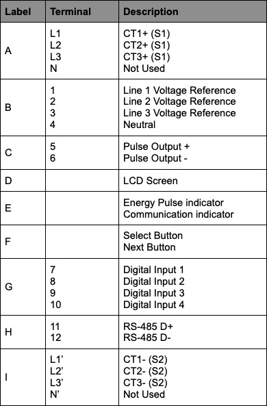
CET PMC-340-BB Three Phase CT Meter Overview
CT Warning - Electrical Hazard
The orange split-core Current Transformers (CTs) supplied with the PMC-340-BB are 5A full-scale and can generate dangerous output voltages and currents when the primary circuit is energised. To avoid this, the CTs must be connected to the meter before the circuits being monitored are energised.
It is recommended to install a CT test and disconnection terminals to allow future testing and maintenance of the CET meter and billing CTs without interrupting supply to the billing circuits.
CET PMC-340 Three Phase CT Meter Wiring Overview
The A6M+One (6M4/MB) and CET PMC-340-BB device should be installed with a three phase breaker or RCBO with a ratio of ≤ 10A for protection and isolation of the power and voltage reference connections as per the local jurisdictional requirements. This is not included as part of the Wattwatchers bundle.
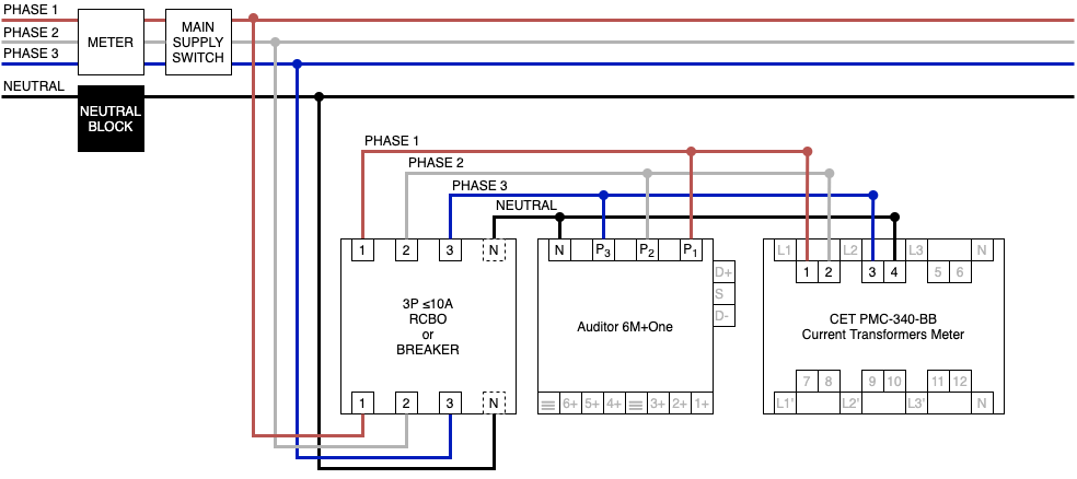
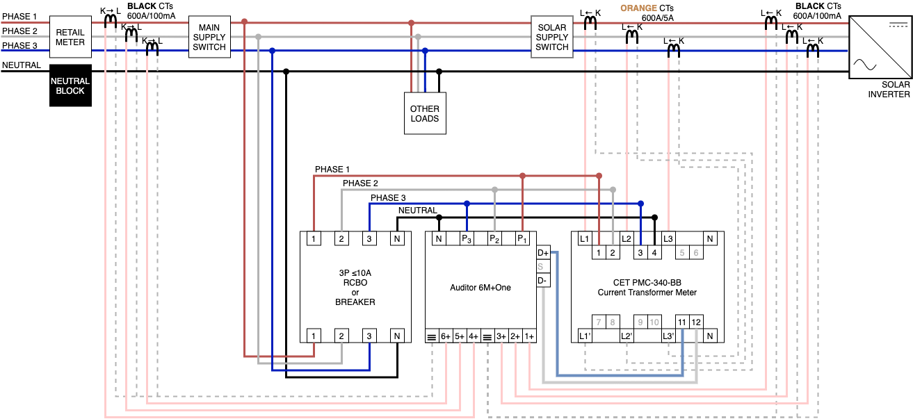
CET 6M+One and PMC 340 Three-Phase Current Transformers Meter Wiring
Note that it is possible to use CTs with a higher rating than 600A, but these are not supplied or directly supported by Wattwatchers and additional configuration changes to the CET meter will be required. Please contact the sales@wattwatchers.com.au for additional information.
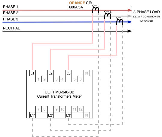
It is important that the wiring of the billing circuit voltage references and CTs is in the correct phase order and in the direction.
The source is always the relevant supply side of the circuit (e.g., grid, solar inverter or generator).
CTs for the CET PMC-340-BB must be clamped to the correct phases of the billing circuit and in the correct direction. The direction is identified by the CT cable colours and by the arrow on CTs going from source (K) to load (L)
Failure to connect voltage references and CTs with the correct phase order and orientation will result in inaccurate power readings such as negative power and incorrect power factor.
For detailed technical information on the CET PMC-340 meter, please refer to the User Manual.
Applications with solar generation (e.g., PPAs and LGCs)
When the CET PMC-340-BB CT meter is being used to monitor a solar inverter or other sources of generation, the grid voltage references are connected to terminals 1, 2 and 3 and the neutral to terminal 4 on the top of the meter.
The positive (pink) wire of each CT is connected to the L1, L2 or L3 terminals on the top of the meter.
The negative (white) wire of each CT is connected to the L1’, L2’ or L3’ terminals on the bottom of the meter.
Note that the arrow of each CT is pointing away from the source of generation. This is to ensure that the solar generation is recorded as positive energy flowing through the meter.

Applications with load (e.g., EV charging, tenant consumption monitoring)
When the CET PMC-340-BB CT meter is being used to monitor load consumption, the grid voltage references are connected to terminals 1, 2 and 3 and the neutral to terminal 4 on the top of the meter.
The positive (pink) wire of each CT is connected to the L1, L2 or L3 terminals on the top of the meter.
The negative (white) wire of each CT is connected to the L1’, L2’ or L3’ terminals on the bottom of the meter.
Note that the direction of the arrow of each CT is pointing towards the load.
CET Meter Current Transformer Specifications
Details of billing CTs are given in the table below.
|
Size (Amps) Max circuit rating / CT output ratio |
Opening Width (mm) Max conductor size inc. insulation (cable or busbar |
Cable length (m) Max cable distance from CET meter to CT |
|
600A / 5A |
36 mm |
2.8 m |
Extension of the billing CT cables should be avoided and the existing length should be treated as the maximum allowed from CET meter location to where the CTs are clasped over the billing circuit conductors.
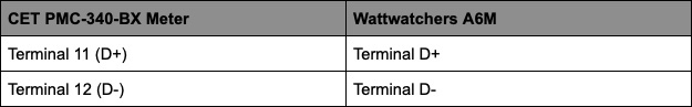
Modbus communications connection to Wattwatchers A6M
The RS-485 Modbus communication from the CET PMC-340 meter is connected to the Wattwatchers A6M+One Modbus interface by connecting the data terminals together as shown.
The shield (ground) terminal ▽ of the Wattwatchers A6M+One does not normally need to be connected.
A 120Ω termination resistor is included with the CET meter that is optional and is not normally required for short cable lengths.
CET Meter Configuration
All CET meters are preconfigured in the factory ready for use with the A6M+One equipment.
For reference, the configuration includes:
- Password set to 0000
- Wiring mode set is 3 phase 4 wire (3P4W)
- Modbus Device ID 100
- Serial Baud Rate 9600
- Serial Communications Port Data Format 8E1
- The transformer-coupled PMC-340-BB CET meter is preconfigured with a CT ratio of 600A primary and 5A secondary.
These settings must not be changed unless this has been advised by the Wattwatchers support team.
Wattwatchers A6M+One Connections
A6M+One minimum power connections
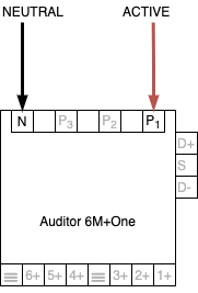
If the additional non-billing circuit monitoring is not required, then the minimum connections required to power the device are a line (active) connection to P1 and neutral connection to the N terminal of the Wattwatchers A6M+One.
The A6M+One (6M4/MB) should be supplied from a ≤ 10A breaker or RCBO to allow the device to be isolated for maintenance and support.
A6M+One Three Phase CT voltage reference connections
When the A6M+One Three Phase CT billing solution is used, it is recommended to provide the power and voltage reference connections from a single Three Phase breaker or RCBO with a rating of ≤ 10A to provide protection and isolation for maintenance.
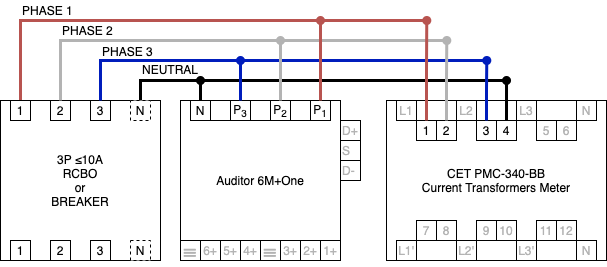
Note that in the above diagram, the Neutral on the Breaker or RCBO applies to RCBO devices only. That being said, port 4 of the CET device is required to be connected to the neutral line.
This arrangement would usually be installed on the load side (downstream) of the main switch or breaker supplying the load or generation being monitored.
A6M+One additional non-billing circuit monitoring
For each of the A6M+One billing solutions, the CET meter must monitor the billing circuit. The Wattwatchers A6M+One provides the 4G communications for remote monitoring of the CET meter and also has its own non-billing submetering capability for up to 2x three phase circuits or up to 6x single phase circuits. This would require the non-billing CTs to be connected to the A6M+One.
It is generally recommended to install non-billing monitoring on the same billing circuit being monitored by the CET to view the data in the Wattwatchers Dashboard web portal and Fleet tools. Although this does duplicate the monitoring, this enhances the ability to remotely monitor and support this site because the CET billing meter data is only available via the Wattwatchers API and not in the Wattwatchers Dashboard web portal and Fleet tools.
Use of the metering inputs on the A6M+One requires additional Wattwatchers split-core CTs to be installed for each input to be monitored. These are available in sizes ranging from 60A to 600A and must be ordered separately if required.
An example of this is shown in the following wiring diagram where an A6M+One Three Phase CT billing bundle is monitoring the following:
- Billing monitoring of solar generation (CET PMC-340-BB Meter)
- Non-billing monitoring of solar generation (non-billing CTs on Channel 1, 2 and 3 of A6M+One (6M4/MB))
- Non-billing monitoring of grid import/export (non-billing CTs on Channel 4, 5 and 6 of A6M+One (6M4/MB))
Please refer to the complete system wiring diagrams section for examples of how to install the non-billing circuit monitoring.
If you require additional monitoring more than the single Auditor allows, or to monitor circuits further than the recommended cable length, then additional independent Auditors can also be individually purchased.
Wattwatchers Auditor Current Transformer Specifications
|
Size (Amps) Max circuit rating / CT output ratio |
Opening Width (mm) Max conductor size inc. insulation (cable or busbar |
Cable Length (m) Nominal cable length from A6M+One (6M4/MB) meter to CT |
Maximum Cable Length (m) Max cable length from CET meter to CT |
|
60 A / 80 mA |
10 mm |
1.6 m |
10 m |
|
120 A / 100mA |
16 mm |
1.6 m |
10 m |
|
200 A / 100mA |
22 mm |
2.8 m |
10 m |
|
400A / 100mA |
25 mm |
2.8 m |
10 m |
|
600 A / 100mA |
36 mm |
2.8 m |
10 m |
Electricians may extend the non-billing CT cables up to 10m total length, or to shorten cables if necessary however this should be avoided where possible.
Please also refer to the Wattwatchers A6M+On Quick Start guides for more information on the installation requirements and capabilities of this device.
Warning on CT Compatibility
The Current Transformers used for the CET Meter and Wattwatchers Auditor devices are NOT compatible or interchangeable.
The CTs used for Wattwatchers Auditors (including those for 600A primary input) are rated to provide 100mA output and are NOT compatible CET meter inputs.
The 600A/5A CTs used for the CET meter are rated to provide 5A output and WILL cause damage if these are wired into the Wattwatchers Auditor device.
The output of the 600A/5A CTs must not be disconnected or left open-circuit when the primary circuit is energised as dangerous voltages may be present and may create an electric shock or electrocution hazard.
Consideration should also be made to install a CT disconnect and test block to allow for any future testing or maintenance of the CET meter to be performed without an outage or interruption to the billing circuits. This is not included as part of the Wattwatchers bundle.
Purchasers and installers must ensure they do not mix up the 600A/5A billing CTs and the non-billing CTs. The current ratio should always be double-checked on all CTs prior to installation and during device commissioning.
Wattwatchers does NOT warrant damage to hardware caused by improper installation where an installer has failed to follow all instructions as directed, mishandled or wired components incorrectly, used parts for an unintended purpose, or used alternative unapproved parts (e.g. CTs). All warranty will be voided under these conditions.
Complete System Wiring Diagrams
The following complete system wiring diagrams are shown with both the billing and non-billing circuits being monitored.
- A6M+One Single-Phase billing bundle with solar monitoring
- A6M+One Single-Phase billing bundle with load consumption monitoring
- A6M+One Three-Phase Direct Connect Solar PPA/Billing bundle with solar monitoring
- A6M+One Three-Phase Direct Connect System Wiring Diagram with Solar and Consumption Monitoring
- A6M+One Three-Phase CT Solar Generation billing bundle with Solar Monitoring
- A6M+One Three-Phase CT Load billing bundle with consumption monitoring
- A6M+One Three-Phase CT Solar Generation Billing Bundle with Solar Generation and Consumption Monitoring
Billing bundle installation process
The following is a high level summary of the steps required to install the A6M+One (6M4/MB) billing bundles. Please refer to the previous sections in this document for specific information about each type of installation and wiring instructions.
- Remove all packaging and check that all equipment including the Wattwatchers A6M and CET PMC meter are in good condition.
- Verify the devices are the correct type for the application.
- A6M+One Single Phase billing bundle for single phase applications up to 63A.
- A6M+One Three Phase Direct Connect billing bundle for three phase applications up to 100A per phase.
- A6M+One Three Phase CT billing bundle for three phase applications up to 600A.
- Mount the CET PMC meter and Wattwatchers A6M devices on the allocated DIN rail location.
- Check that the billing circuit and other relevant circuits and supplies have been isolated and de-energised
- For Single Phase and Three Phase Direct Connect billing bundles, connect the billing circuit cables in series through the CET PMC meter terminals as per the wiring diagram.
- For the Three Phase CT billing bundle, connect the voltage references and Current Transformers (CTs) to the meter terminals as per the wiring diagram. Note that the billing CTs provided for use with the PMC-340-BB are labeled 600A/5A and must be checked to confirm they are the correct type before completing the installation.
- Mark or label each of the billing CT cables at each end so that it is easy to identify the billing circuit and phase that they will be aligned to.
- Install a breaker or RCBO with rating of ≤ 10A to power the A6M+One meter in a parallel feed from the billing circuit. For the A6M+One Three Phase CT billing bundle, this breaker or RCBO can supply both the A6M and CET meter voltage reference connections.
- Connect the supply cables to the Wattwatchers A6M+One device voltage terminals.
- If required, connect the additional voltage references and non-billing current transformers to the Wattwatchers A6M+One device for the additional non-billing circuit monitoring.
- Mark or label each of the non-billing CT cables at each end so that it is easy to identify the billing circuit and phase that they will be aligned to.
- Check the circuit connection phase order and orientation or all connections match the wiring diagram.
- Ensures that all CTs are fully clipped and closed.
- Energise the equipment check the Wattwatchers A6M status LEDs to confirm normal operation.
- Validate the readings using the Wattwatchers Onboarding application and a clamp meter.
- Ensure that the voltage and current readings are in the expected range.
- Australian Voltages are normally in the range of 220 V to 250 V. - Ensure that the power factor values are in the expected range.
- Solar generation should generally be monitored as positive energy flow and is indicated by a positive energy flow and should have a power factor of between 0.8 and 1.0 if the inverter is performing correctly.
- Negative power factor values indicate reverse energy flows. This should generally only be visible on grid connections to indicate energy is being exported into the grid.
- Ensure that the voltage and current readings are in the expected range.
- It is recommended that a photo be taken showing the CT model and cable labelling for future reference and support
Onboarding and device configuration
The devices should be configured using the Wattwatchers Onboarding application that is used for all Wattwatchers devices.
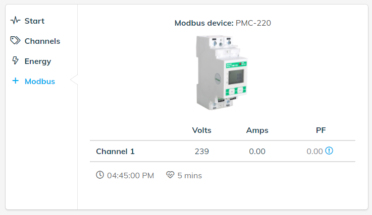
The Modbus step in the Onboarding application provides access to confirm the voltage, current and power factor being measured by the CET billing meter.
The Modbus step does not require any user input as the connected device will be detected automatically. Information on the connect device type, including an image of the device will be displayed.
CET PMC-220 Single Phase Meter Example Onboarding Screen
CET PMC-340 Three Phase Meter Example Onboarding Screen

If there is an issue with the connection between the Auditor and Modbus device, then the following message is displayed.

The Modbus cable connections between the Wattwatchers Auditor and CET meter should be checked and if the issue persists please contact Wattwatchers support.
Please refer to our Onboarding User guide for more detailed information.
CET Meter Documentation
- CET PMC-220 Single Phase Meter User Manual
- CET PMC-340-BA Three Phase Direct Connect Meter User Manual
- CET PMC-340-BB Three Phase CT Meter User Manual
More information or support
Our technical team is available for urgent matters (such as where an installer is actively troubleshooting onsite) from 09 AM to 5 PM, Monday to Friday, AEST/AEDT on 02 8316 7540 (+61 2 8316 7540 from overseas).
For all other enquiries, please first check our Support Page.