How to use the Onboarding tool video
Every Auditor device must be onboarded once the installation is complete! The Wattwatchers Onboarding tool gives you the information required to validate that an installation's readings are accurate.
Onboarding can be accessed at wattwatchers.app
Prerequisites for commissioning
1. You need an Onboarding account and you need access to the device in wattwatchers.app before installation.
2. A smartphone or computer with an internet connection is required as the device is commissioned via the cloud.
3. The Auditor must have adequate signal strength and an internet connection.
To validate readings, the Auditor must be powered and the circuits must have load.
A quick guide on how to commission an Auditor device
Here you will find a quick guide on how to commission the Auditor device. If you would like a full comprehensive guide, please see our link > Comprehensive Onboarding User Guide
The basic steps to setting up an Auditor device are:
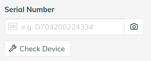
1. Log into Onboarding and enter the serial number of the Wattwatchers device.
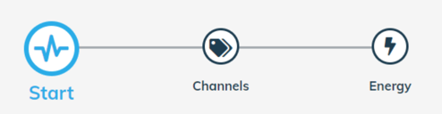
Use the menu icons to move between each section of Onboarding.
2. On the Start page, give the device a name and choose the local timezone and the antenna type.
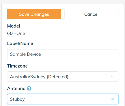
Tap on the Save button before moving to the next step.
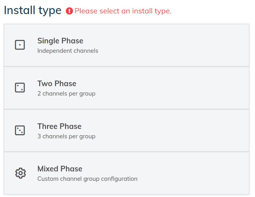
3. On the Channels page:
a. First select the installation type - Single Phase, Two Phase, Three Phase or Mixed Phase.
b. Then for each channel:
i. Select the Channel Type (such as Grid, Solar, Power, Air Conditioning, etc)
ii. Select the CT Rating (eg: 60A, 120A, etc)
iii. Give the channel a user friendly name in the Custom Label field.
iv. Repeat this process for all CT channels that are installed.
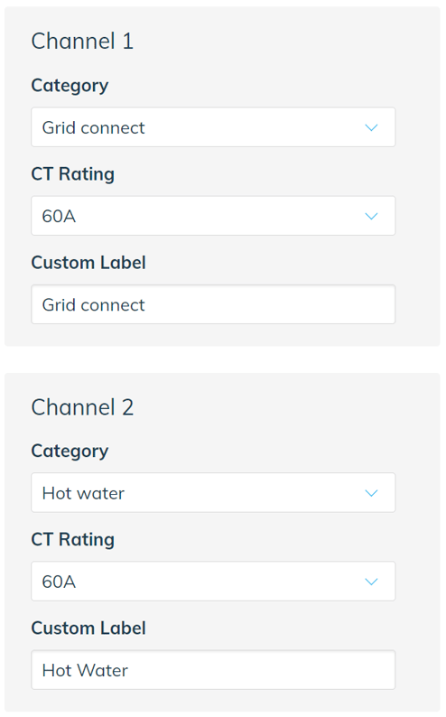
Tap on the Save button before moving to the next step.
4. Use the Energy page to commission the Auditor as described in the next section.
Commission an Auditor
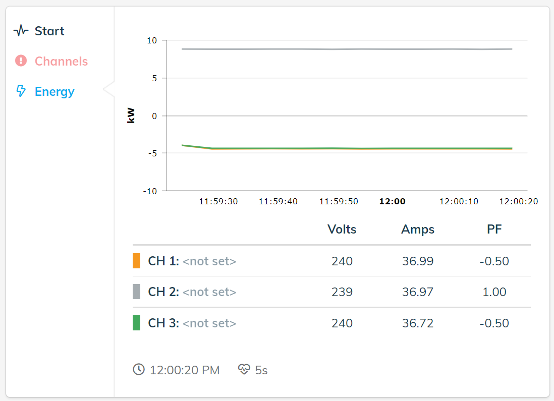
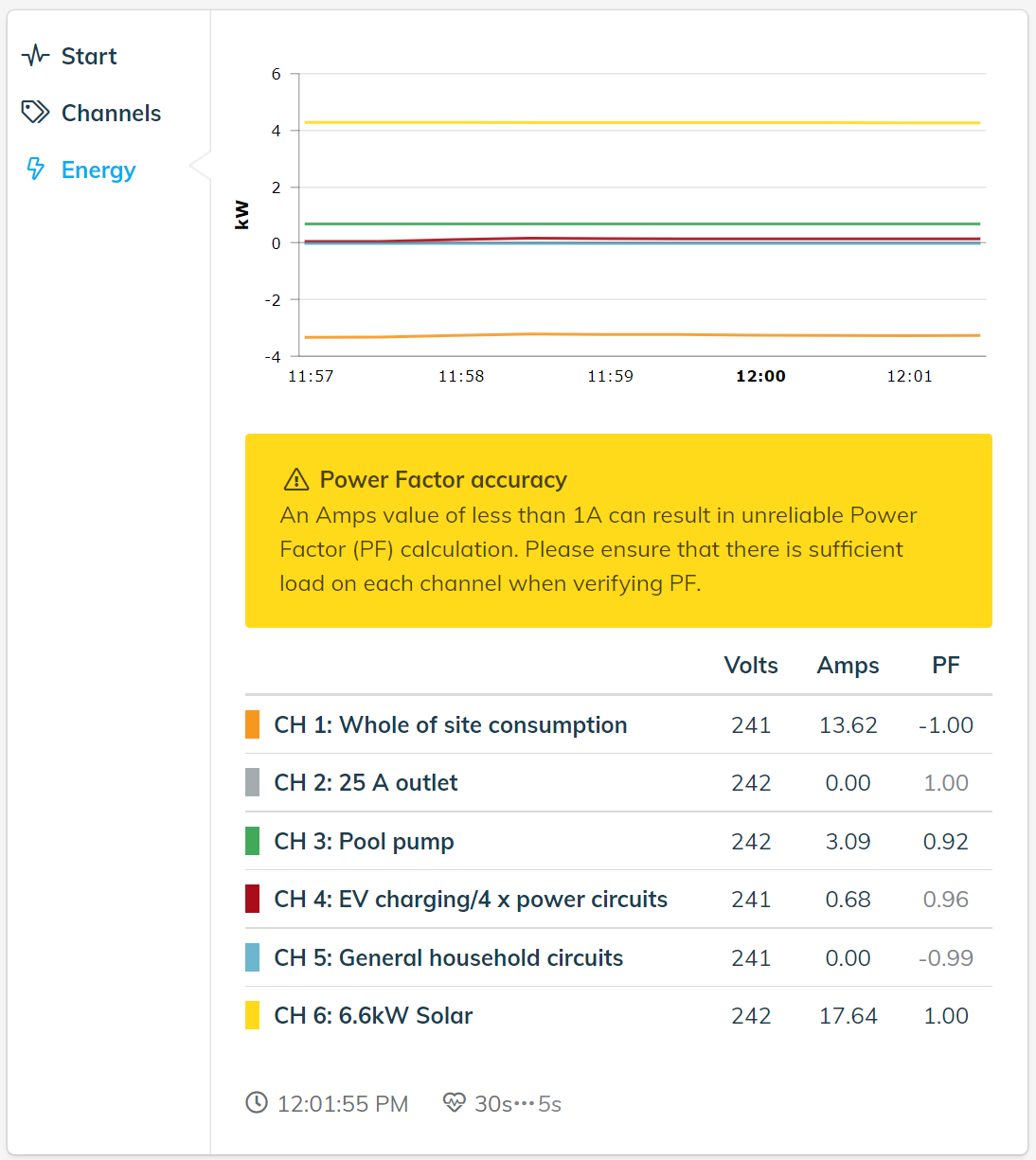
The Energy step in Onboarding shows live readings for Volts, Amps and PF.
The Chart shows kW.
Positive values on the kW chart generally indicate normal energy consumption.
Negative values on the kW chart generally indicate reverse power flow on that channel, or that a solar system is exporting to the grid.
Use the Power Factor (PF) values to confirm if the phase and direction of each channel is correct.
TIP: Power Factor (PF) is a valuable diagnostic tool
A Grid channel should normally have a positive PF for load that is consumption from grid.
A Grid channel will show a negative PF if there is a solar system exporting to the grid.
A negative PF on a load is likely to be incorrect, and is commonly a sign of a CT fitted backwards or on the incorrect phase.
Poor PF (<0.8), particularly if on multiple phases, is often a sign that CT's are placed on the incorrect phase. Some loads can legitimately have readings below 0.8 so you'll have to interpret this in context.
Solar inverters will have PF close to 1.0 when generating energy.
Recommended steps in a commissioning process
- In the Start step ensure that signal strength is adequate. Determine if you need an extended range antenna.
- Turn any solar systems off to check the grid reading - this prevents erratic readings if exporting.
- Check the kW chart - Negative readings on circuits without solar indicates an issue.
- Check the PF readings for low and negative readings - This could be incorrect CT placement.
- Check the Volts measurement against a multi-meter.
- Check the kW and Amps readings with a clamp meter.
- Use screenshots from the Onboarding tool as supporting documentation when you close a job.
Examples
A6M Examples
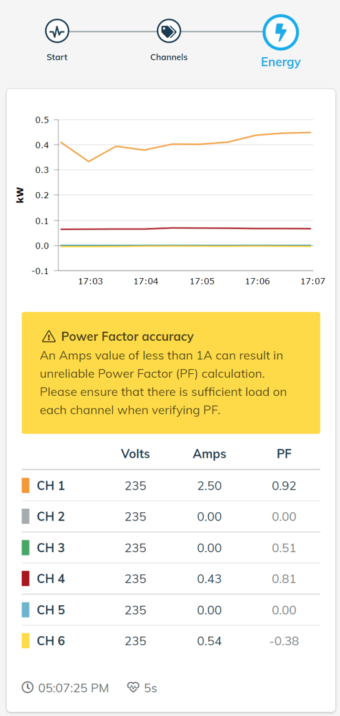
Single phase with solar correct installation
Correct monitoring of all channels. CH1 PF -1.0 as site is exporting to grid. CH6 Solar PF 1.0. CH3 Pool pump PF 0.92 is acceptable. Other channels can be ignored for circuits with <1A of load.
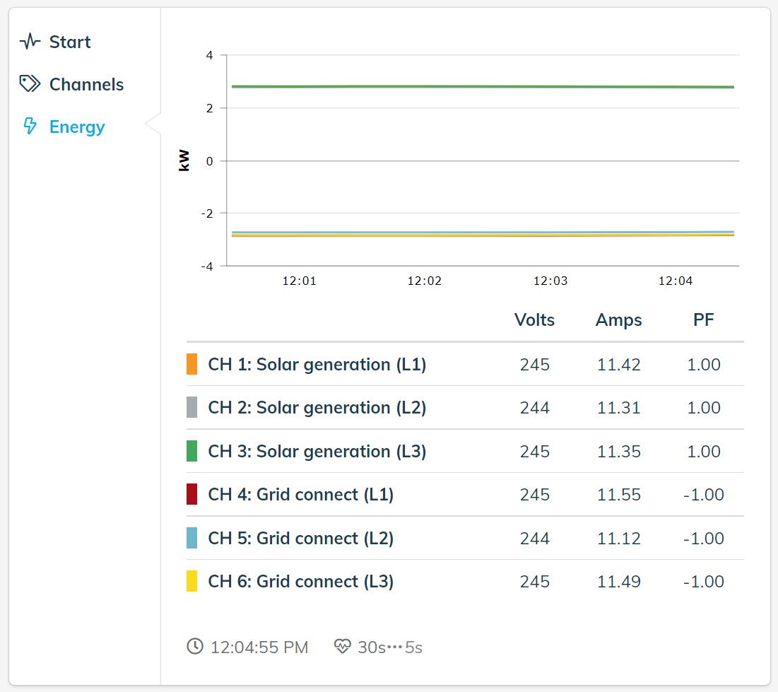
Three phase with solar correct installation
Correct monitoring of all channels. Solar channels PF 1.0. Grid channels PF -1.0 as energy is being exported to grid.
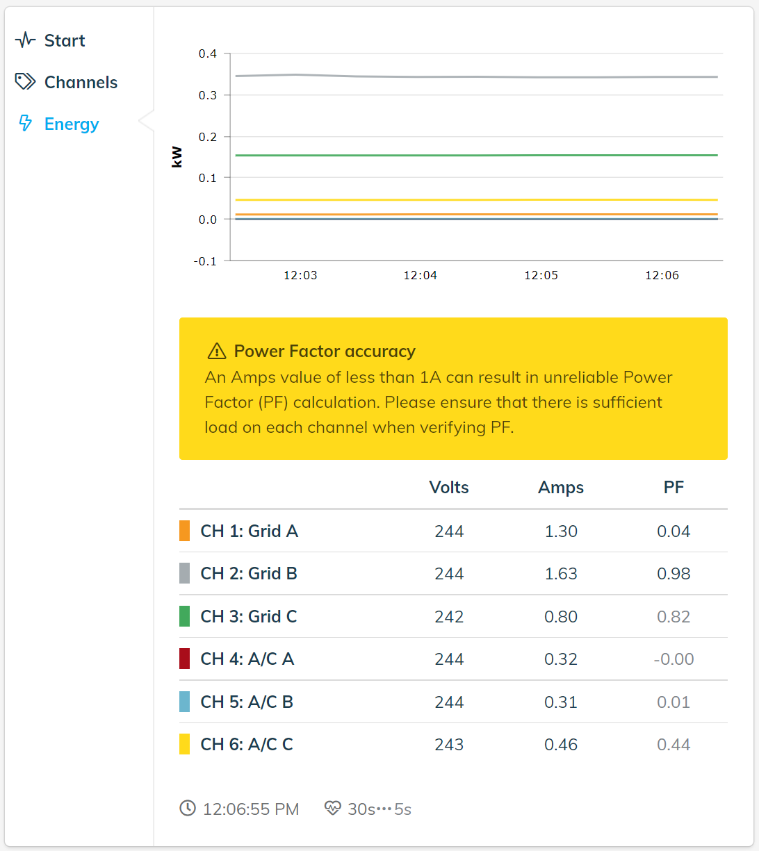
Three phase site incorrect installation with CT phase error
CH1 Grid A PF 0.04 indicates there may be an issue with the phase the CT is monitoring. CH2 Grid B is ok. Not able to validate other channels as load is <1A.
A3R Rogowski Coil Device Examples
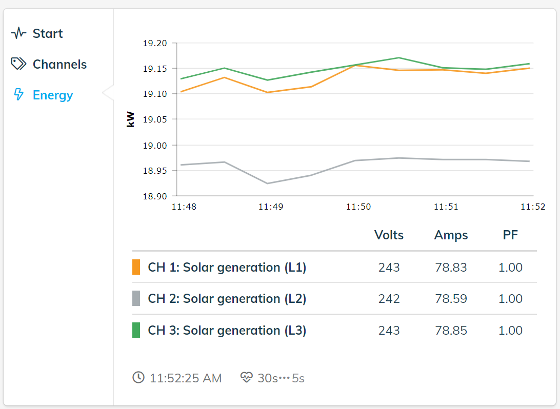
Three phase solar monitoring correct installation
Correct monitoring of solar output with all PF values 1.0
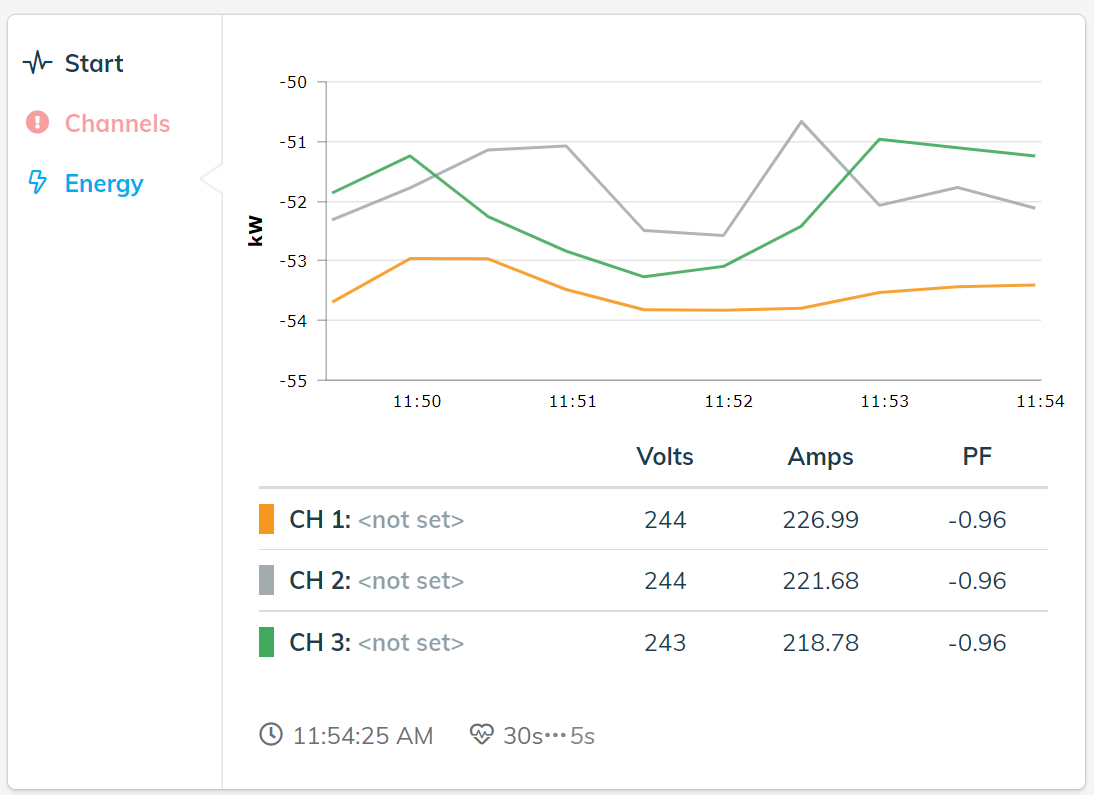
Three phase solar incorrect installation with reversed Rogowski Coils
Incorrect monitoring of solar output as all PF values -1.0 indicating all Rogowski Coils are reversed. Device has not been fully set up in onboarding as channel names are not set.
Three phase grid with incorrect CT phase assignment error
Incorrect monitoring of grid with phase assignments due to varying PF values. Device has not been fully set up in onboarding as channel names are not set. P1 and P3 are swapped (incorrect phase rotation).